DIY Digital Clock
The first thing I wanted to make once I got a 3D printer was a digital
clock. How hard could it be? Turns out it's somewhat hard. It's not
rocket science (I suppose - I'm no rocket scientist), but it's also not
something I could throw together in a week on the first try.
So here's a short story about making your own electronics and stuffing
them into a pretty box with lights and colors.
The Brain
To have a digital clock, you need something to keep track of time and
light up LEDs accordingly. For this, I had some microcontrollers lying
around - namely, the Arduino Nano.

Arduino Nano
A microcontroller is a small computer that runs a single application.
Imagine your phone, but it can only run a calculator app (or just
imagine an actual calculator).
You can write some logic (e.g., light up two dots between digits when
the seconds number is odd, and turn them off when it's even), and you
can connect electronic components - LEDs, in this case - and control
them. Or let a component provide information; for example, a
temperature sensor could tell you... the current temperature.
In my case, I don't have any sensors. What I do have is a component
that tracks time. Why do I need this? Because tracking time isn't as
easy as it sounds, because, well, physics and all that. Also, it has a
battery, so if I unplug the clock and plug it back in, I don't need to
set the time again, which saves me time.
*ba dum tss*
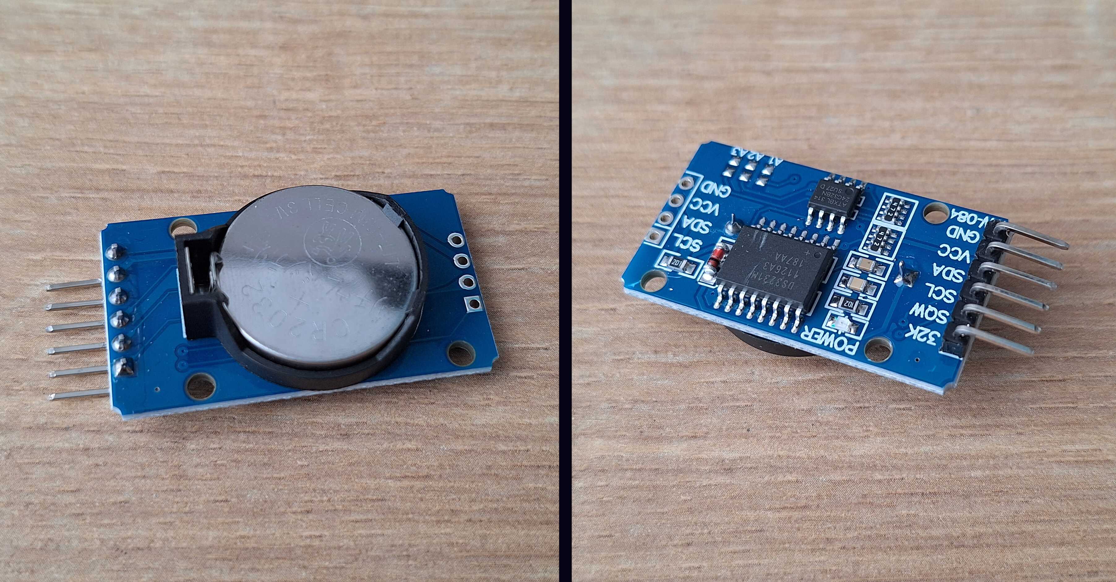
RTC (Real Time Clock) component, tracks time
The Face
You can buy ready-made digital number displays called 7-segment
displays (so called because it takes 7 sticks to make any number). But
these are usually small - I couldn't find ones larger than ~2.5 cm in
height - and I didn't want a clock made for ants. So I figured I'd make
my own display for humans. It's just some LEDs, right?

Ready-made displays for ants
And it is just some LEDs. The problem is connecting all that to an
Arduino board. Four digits with 7 segments each is 28 wires. I also
need a few buttons to set the time, plus 5 wires for the lights on top.
But the Arduino Nano has only 22 inputs - obviously not enough.
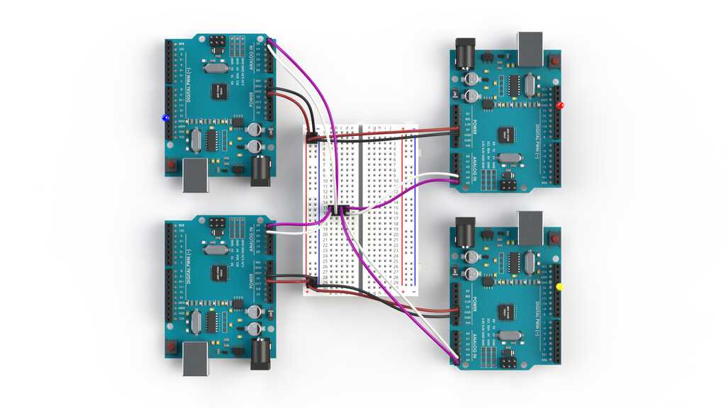
I could connect multiple Arduinos together and split the wires between
them, but thinking about how this amalgamation should work... I'd
rather live in the woods and make cuckoo clocks out of scraps.
Hey, that's actually not that bad... as is living in the woods
That's when I found out about shift registers. It's a component where
you can hook up
many
wires and control them using just a
few. Using this, I can connect all digits using 3 wires instead of 28.
That's
*whips out a calculator*
...multiple times better!
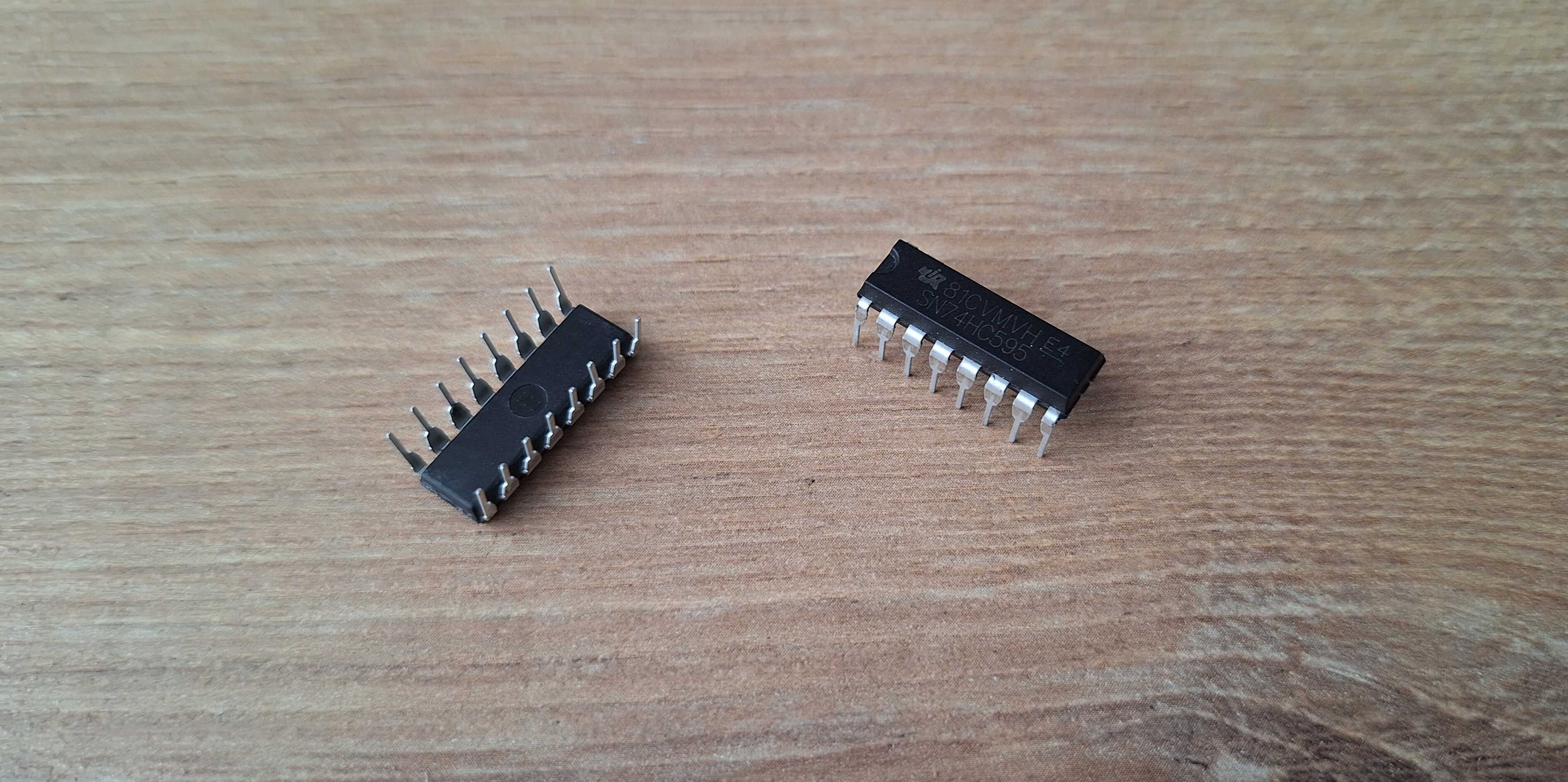
Shift register, like a cockroach of electronics
Even though I now only need to connect a few wires to the Arduino,
there are still a lot of wires going into the shift registers. And a
lot of wires can become a pain later - you'd better get it right on the
first try, or you'll have to debug a rat's nest of wires. It gets
finicky and annoying fast.
That's when I had an idea - couldn't I make one of those boards with
copper tracks instead of wires, like proper electronics are made? Of
course I can. I have the internet and enough fingers to type stuff into
a search bar and figure it out.

Actual electronics
First thing I found - you can buy those boards premade. You do need to
learn how to use software to design them, though, which I didn't know,
and you have to order like 5 boards at a time, which I didn't need.
Next thing I found was how to make them myself using a few chemicals.
The idea is: take a copper-clad board, put ink on it (say, with a black
marker), dip the board in acid, and all the copper not covered in ink
will be etched away. Clean off the ink, and what's left are copper
tracks. So you can draw where your components go, connect them with
lines, and voilà!
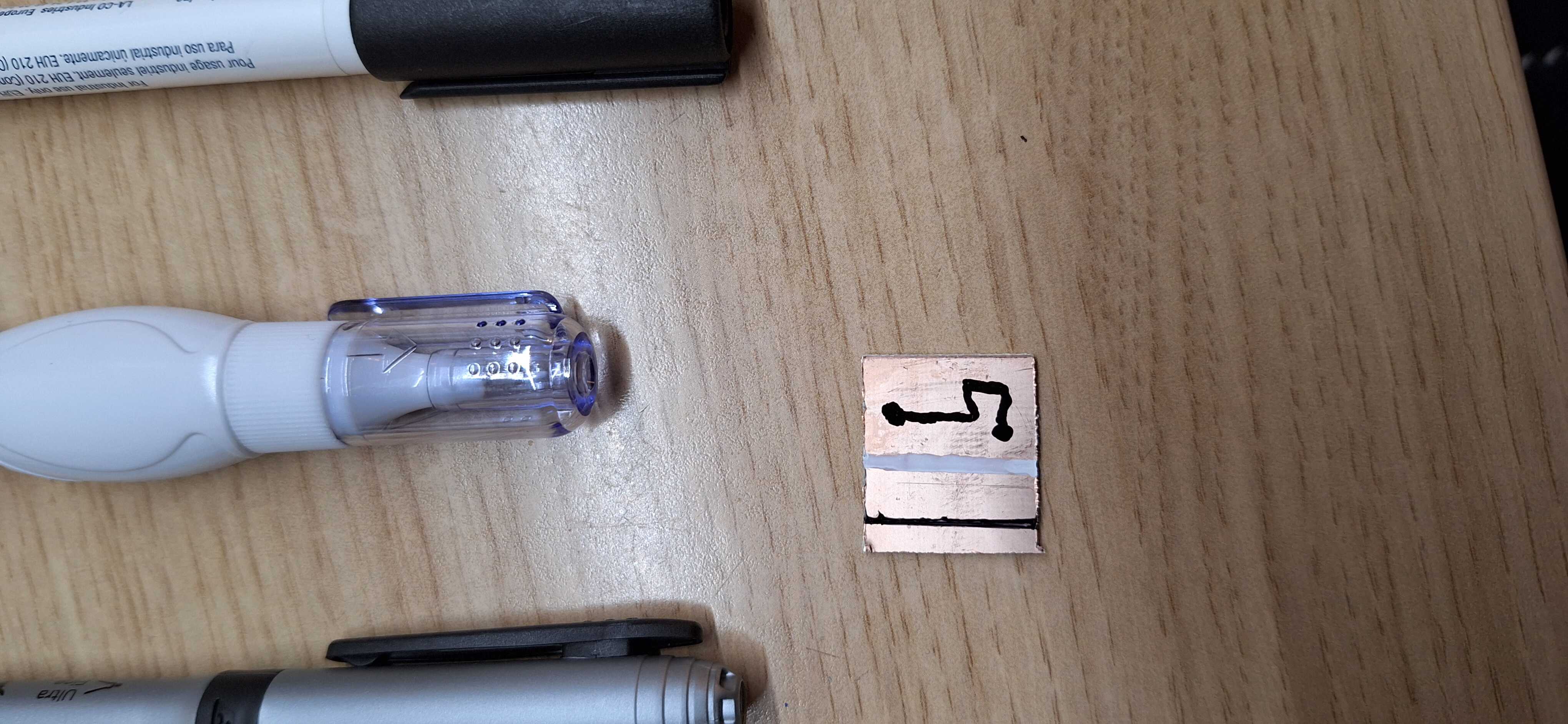
Trying different markers
So I took a board and a marker and started drawing. It's all fun and
games marking places for components - basically drawing 4 digits.
Existential dread kicks in once you start connecting those
components... wires start overlapping, which they shouldn't, so you
start over. Suffice to say, it took me a few tries to realize doing it
this way is a shit idea.
The software for making boards I mentioned earlier? It's called KiCad,
and it does that automatically. You create a schematic outlining how
things should connect, place components as desired, click a button, and
it routes the wires so they don't overlap. Fuck yeah! And it still
takes a while to find the right paths - it would've taken me a year and
a lot of grief to do that by hand.
KiCad auto routing, look at it go!
Next, I took a component layout picture and made a 3D model from it.
Now I have a 3D-printed stencil with holes for components exactly where
they should be, and I can start drilling the copper board.
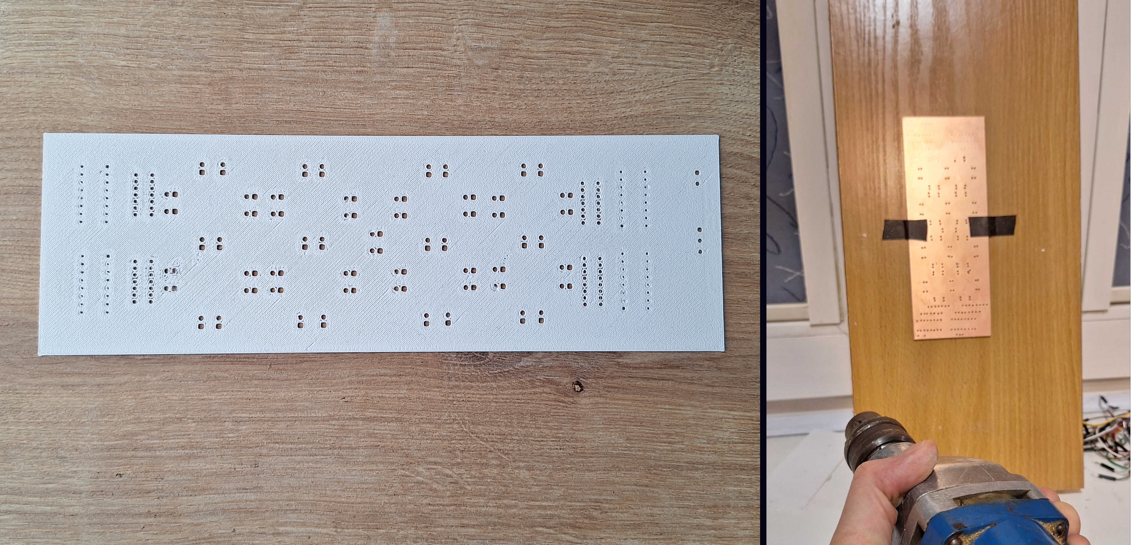
Marked board with a nail and a hammer
After drilling the holes, I tediously followed the auto-routed tracks
in KiCad and drew them by hand between the holes I drilled. It turned
out not too bad - now I can dip this masterpiece in acid.
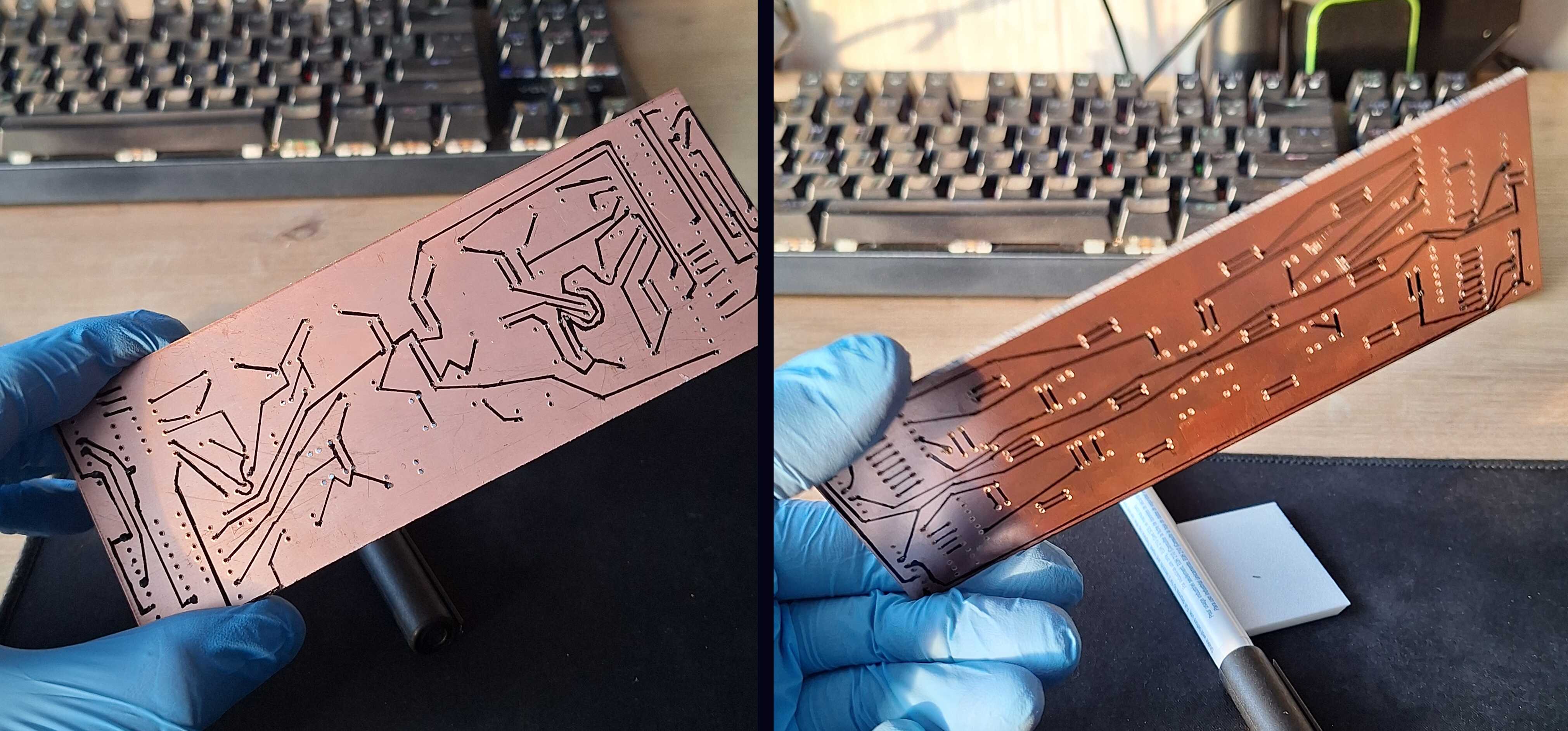
Masterpiece
The most accessible "acid" I found that would etch away copper was a
mix of vinegar, hydrogen peroxide, and salt. It's not exactly acid, but
it acts like it in this case. Dip the board and wait for 20 minutes.
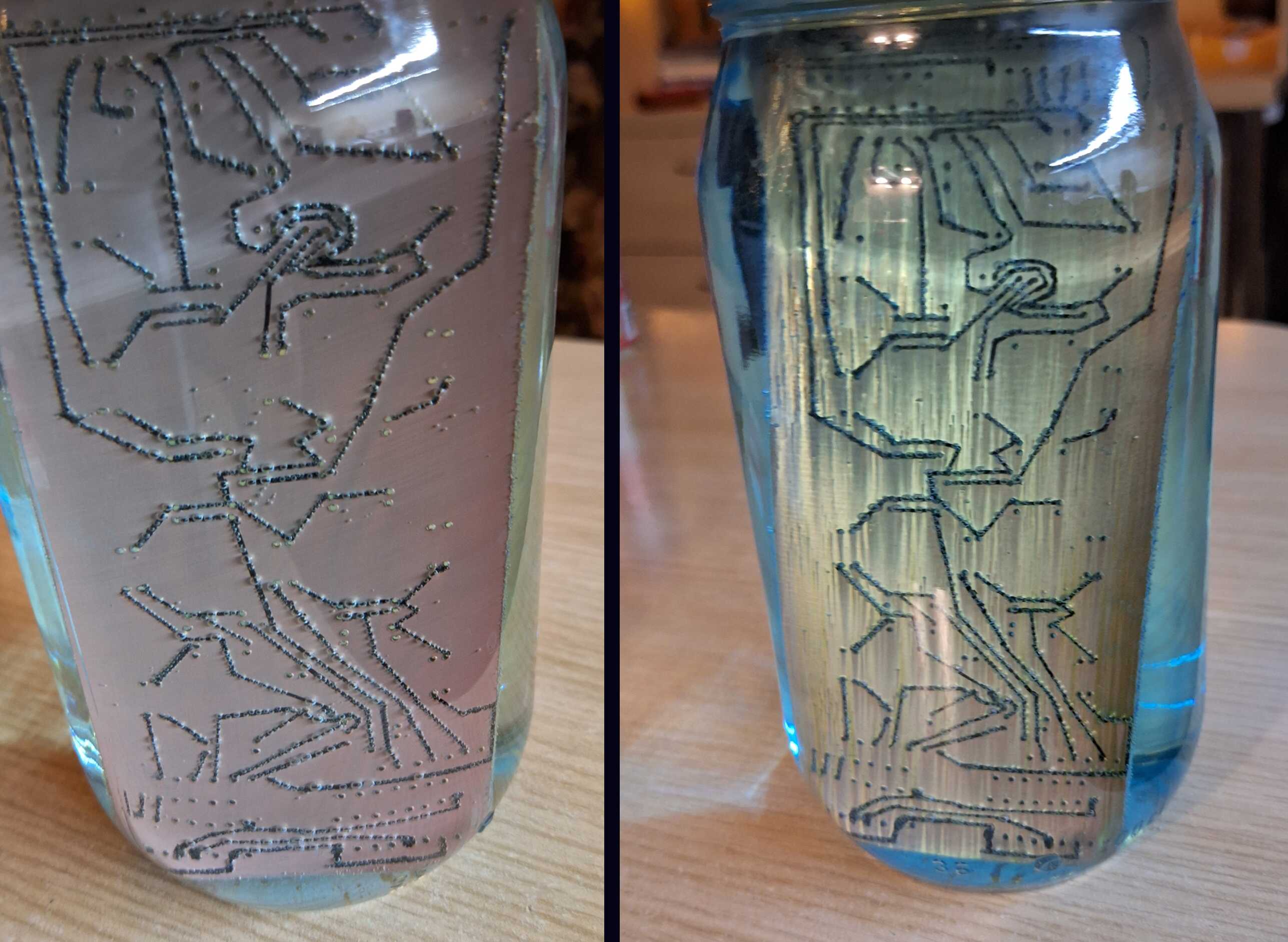
After a few minutes, and then after a few more minutes
Later I found out that this mixture produces poisonous gases -
something people used in World War I (not with friendly intentions).
But hey - it worked, and I found a safer substitute for future
projects.

Got this without dying
After taking the board out of the acid, the marker is still intact.
Once you wipe it away with alcohol, you'll find copper underneath -
neat!
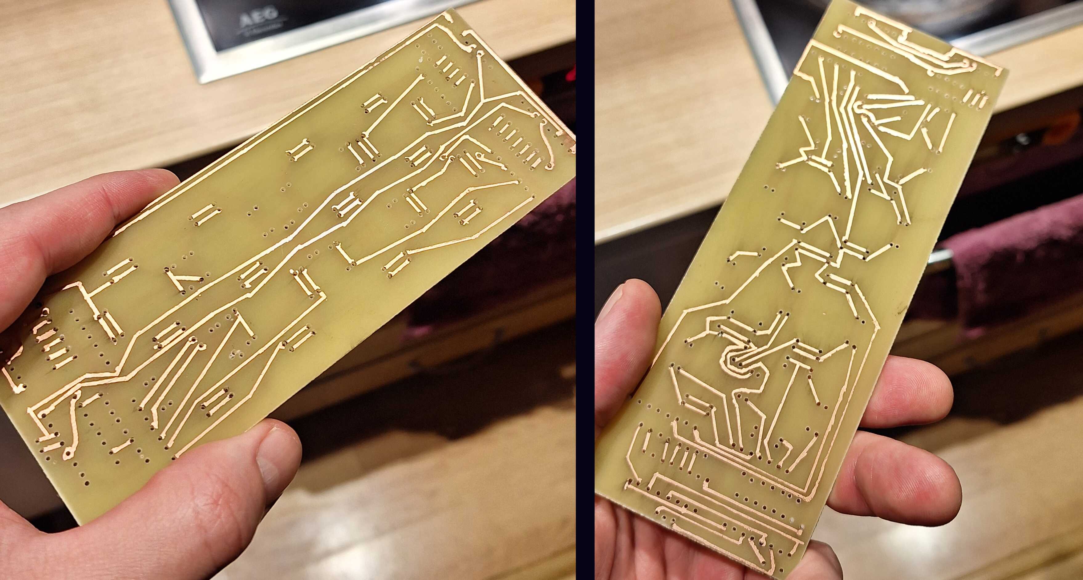
Neat!
Now I've put LEDs, shift registers, and resistors where they're
supposed to be and soldered them to the copper bits that weren't etched
away.
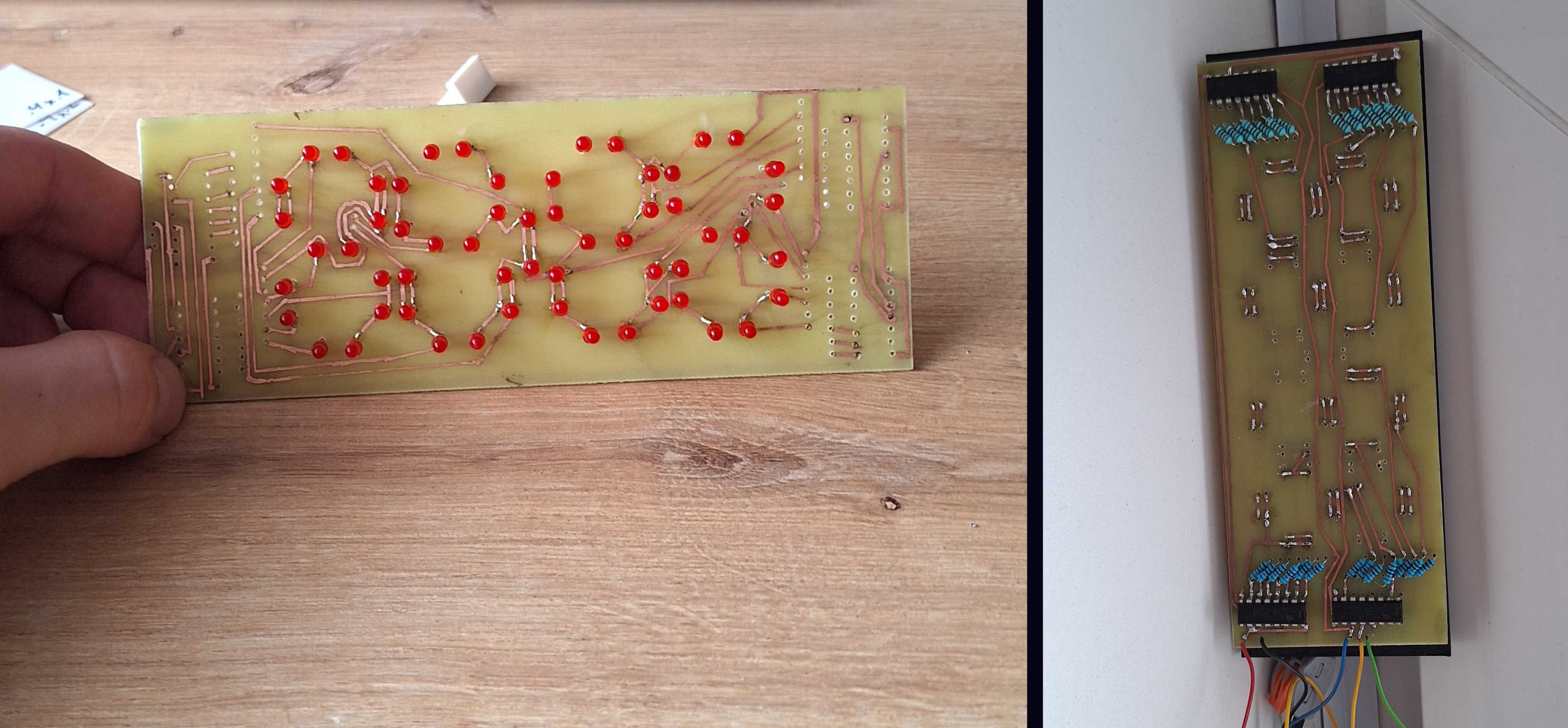
Turn the board on and... only 7 LEDs work. I didn't expect this to work
flawlessly on the first try, but damn...
After checking connections with a multimeter, I found most of the
problems, and now all but one LED works - much better. I'll fix that
one later.

Bad and better
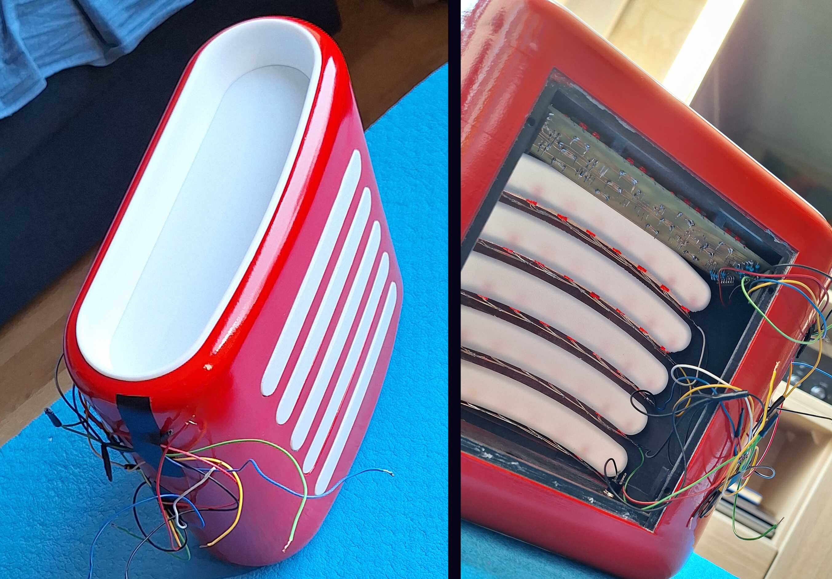
The Grill
"Grill" is what I call the sausage-shaped panels on top of the clock.
These light up every hour, on the hour - except at night. First, I
needed to make a white plastic box to test if and how well the LED
light would shine through.
Test successful
It works! Now I had to experiment with different LED placements to see
which worked best.
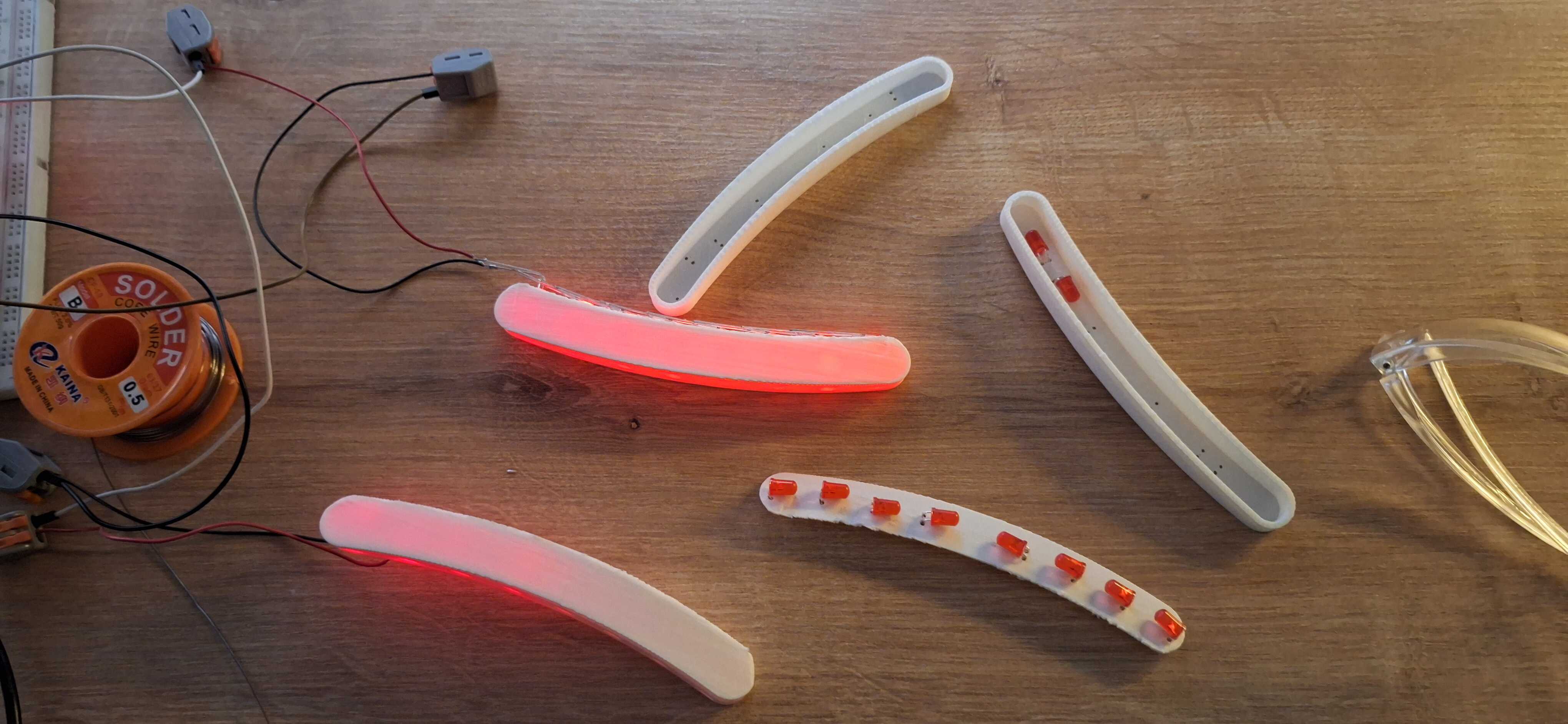
Since these LEDs are less bright when turned sideways, small changes in
placement had a big impact on how bright the sausage looked overall.
Not all sausages are equally bright
The Body
I used FreeCAD for 3D modeling - here's the clock model in all its
glory.
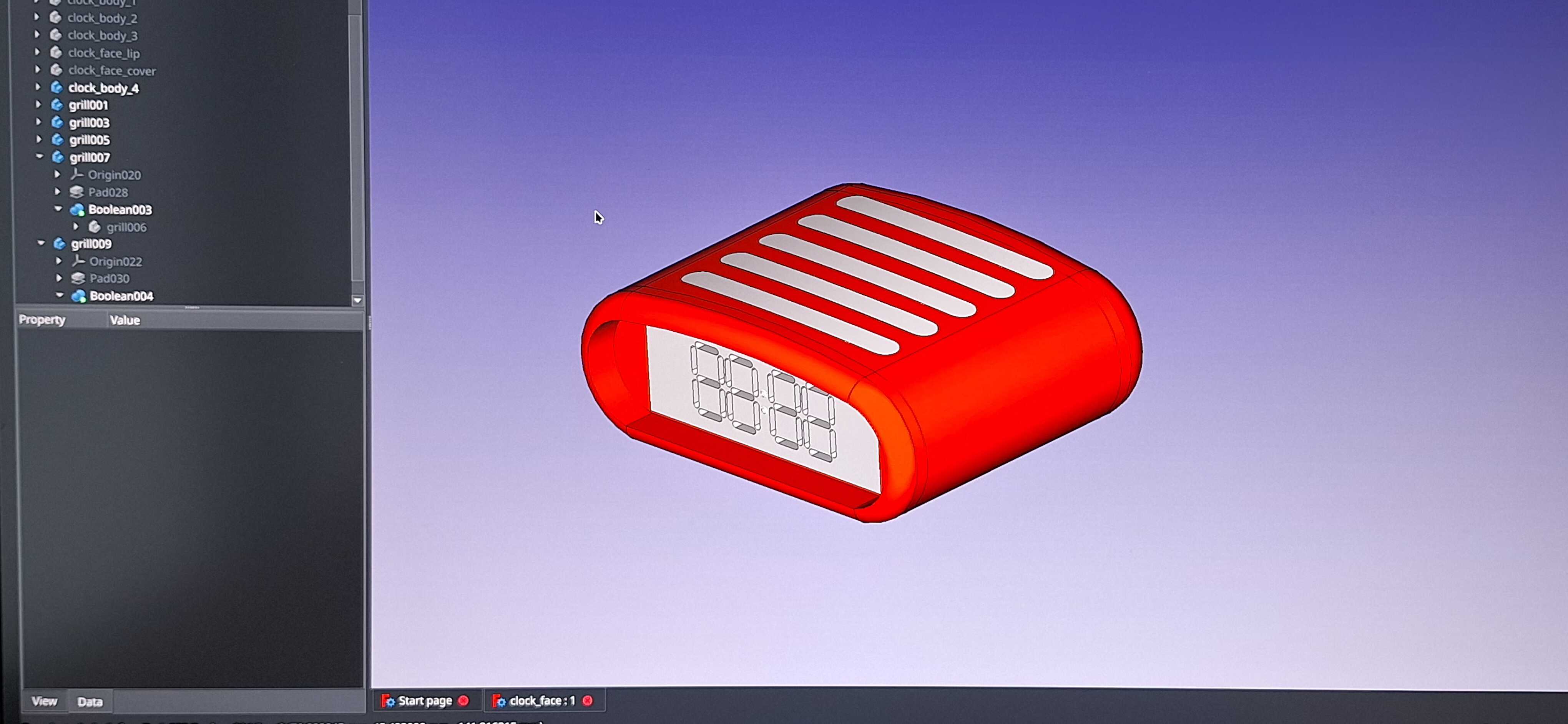
Glorious
I had to make the model twice, because I didn't think about the size
the first time around, and it turned out too big for my 3D printer. So
I redesigned it in three parts - back, front, and middle.
Once printed, I just glued it all together - like building with LEGO,
sans super glue.
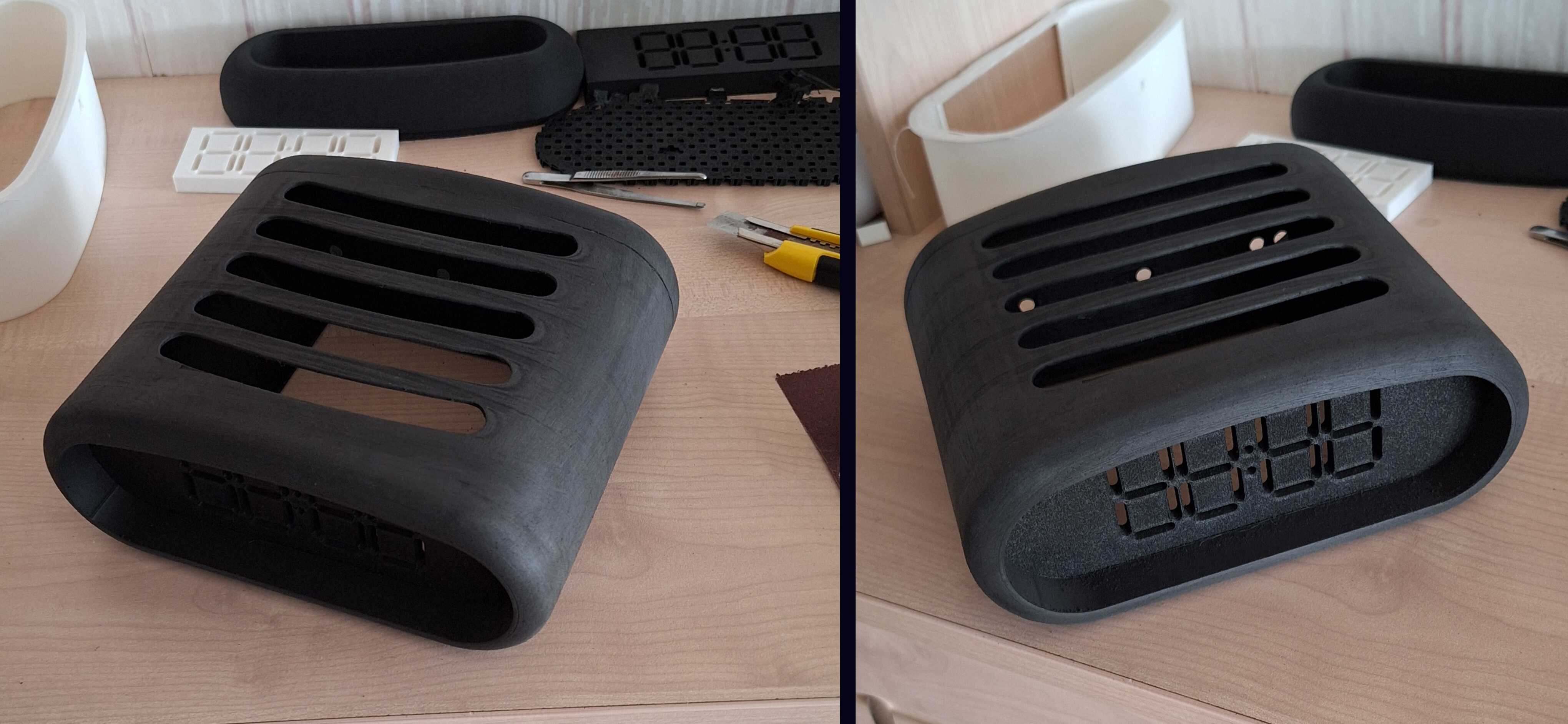
Then I had to get rid of the cracks where the parts come together - so,
some primer and filler.
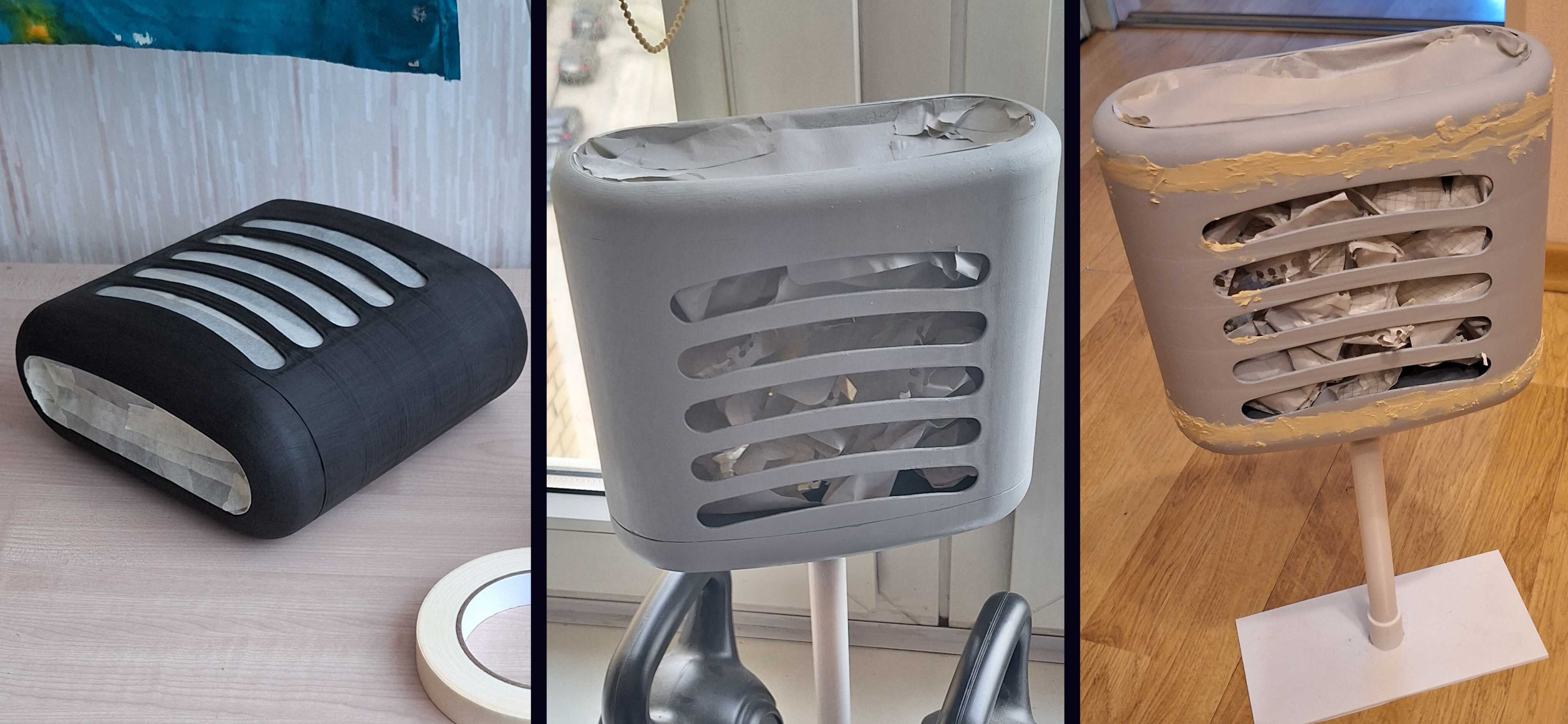
So much filler
That was way too much filler. I spent ages sanding it, but oh well - it
looked good after I put a layer of paint on it.
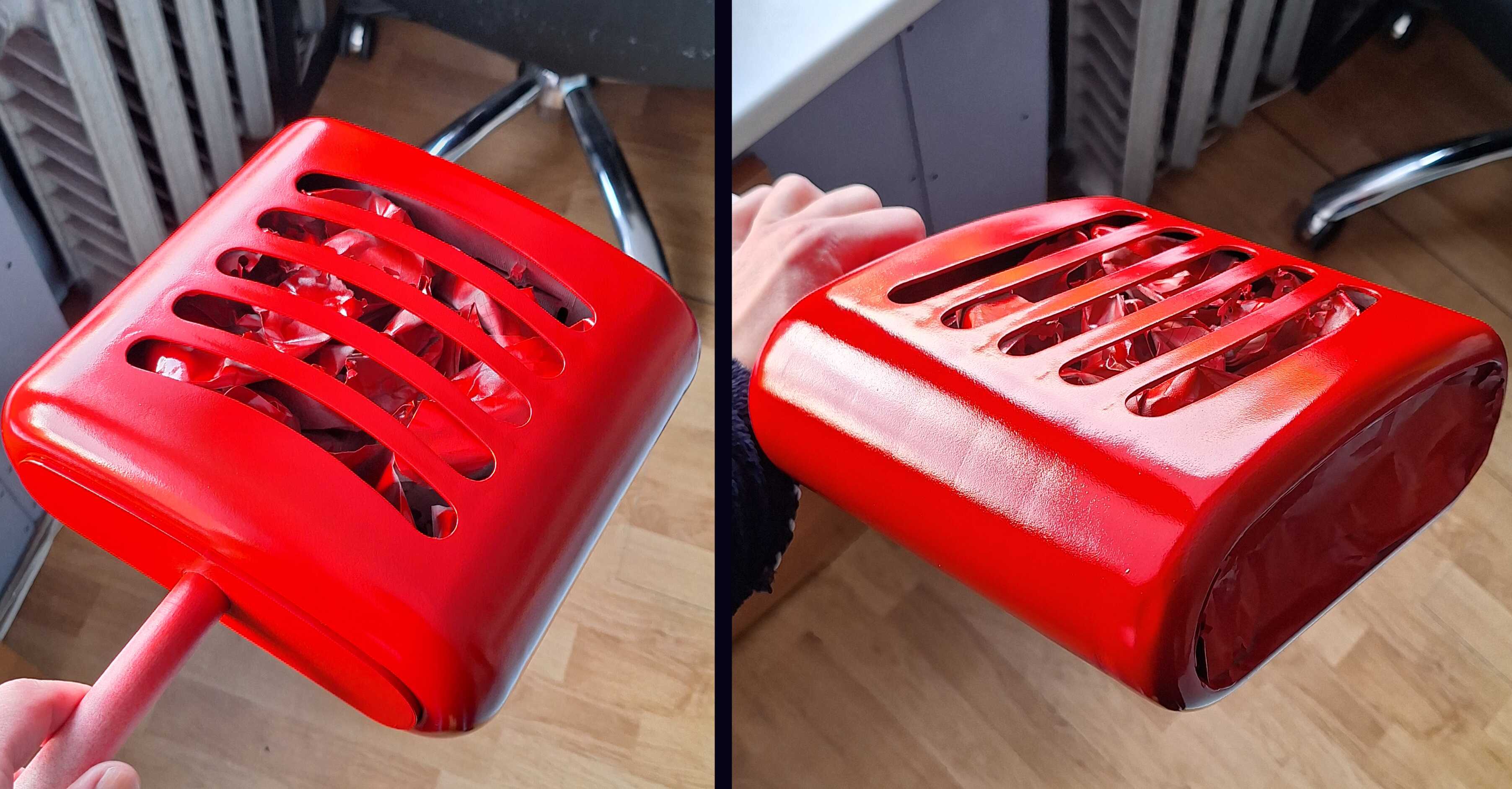
And then, after putting the final layer of lacquer on, a fly landed on
a still-wet spot. That was the end of the fly - and the beginning of my
tears. I figured I didn't want a fly fossil on my clock, so I sanded
that spot, removed all the messed-up parts, and redid the finish.
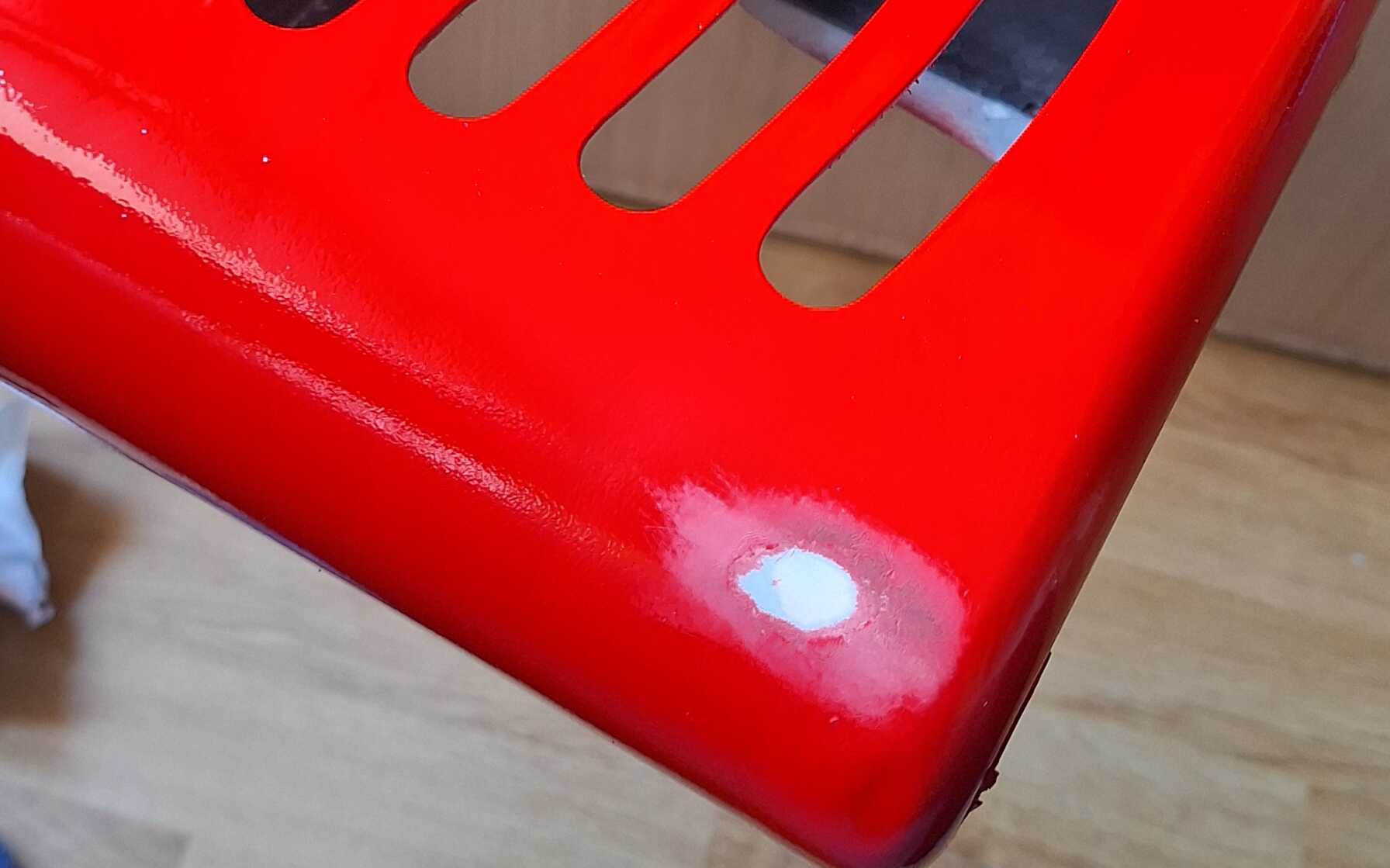
So many tears
What was left was the software part of this thing - making the clock
tick, buttons to change the time, and having the grill light up in
some
animated flowing
kind of way.
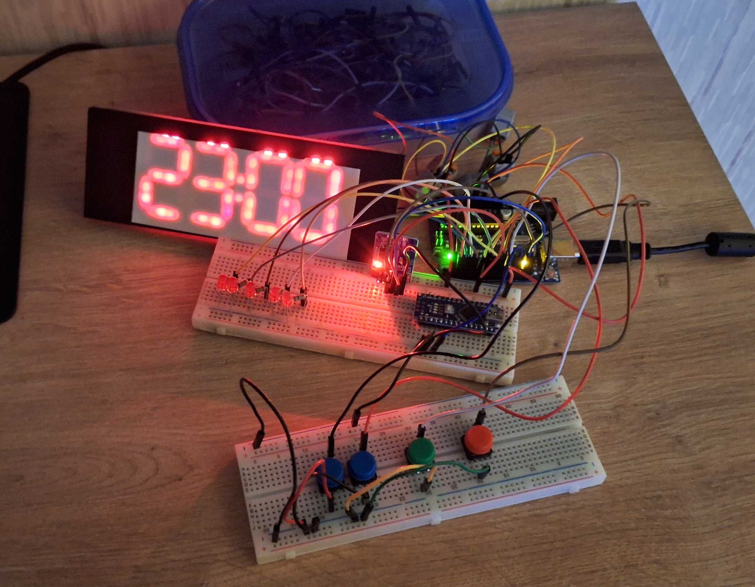
Most of this will be inside the clock
I had everything hooked up outside the clock body, and when I was done
writing the software, I just shoved everything inside.
And that's it - the Cadillac of clocks.
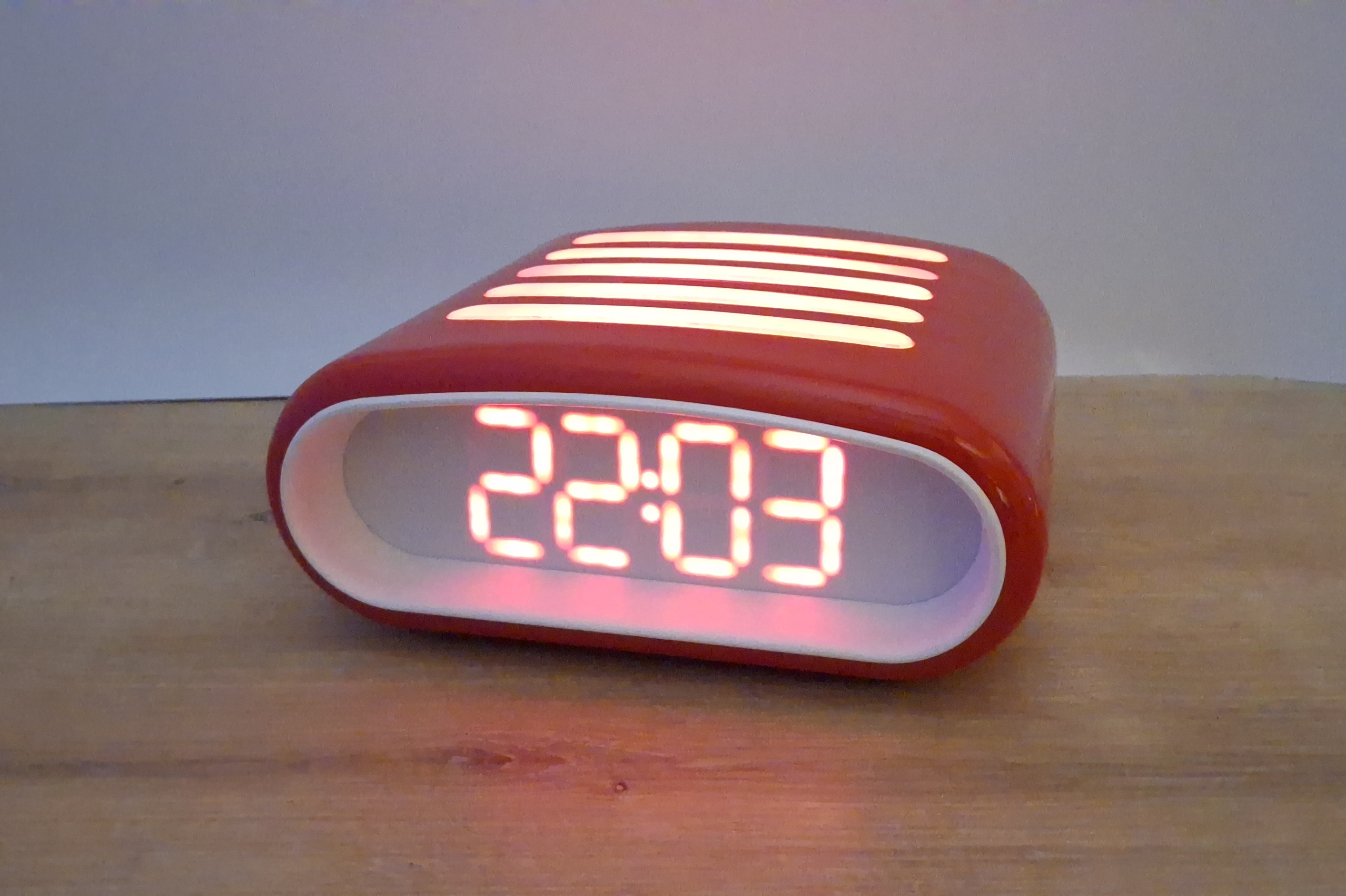
Thanks for reading and let me know if you'd like to get a clock like
this of your own.